Tester-Stim-X3
Overview
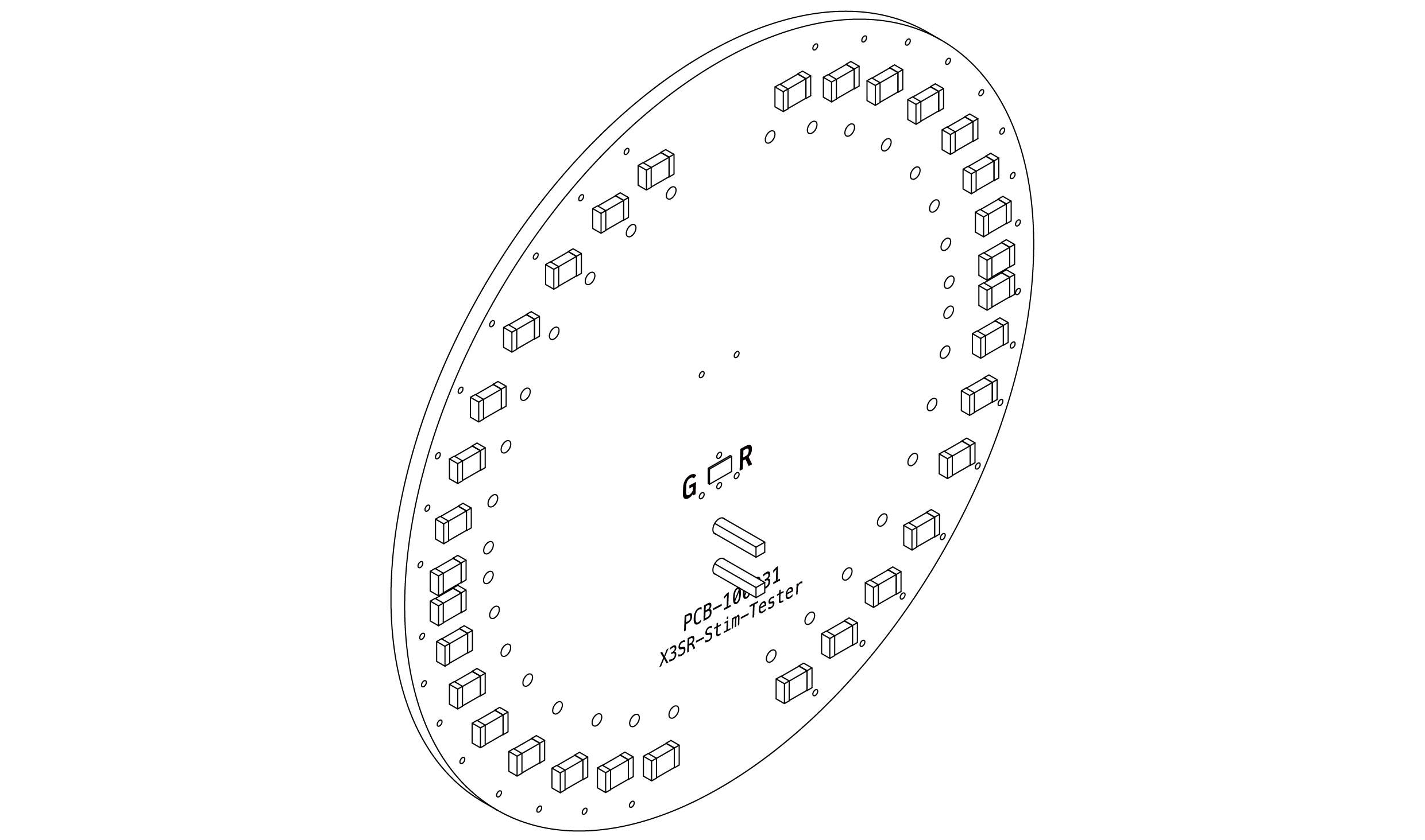
The X3 Headstage Stimulation Test Module is designed to verify the stimulus waveform generated by X3SR headstages. By connecting the module to a dummy 1 kΩ resistive load, users can safely observe and validate stimulation output characteristics without connecting to biological tissue.
Tester-Stim-X3 Overview
Test Operation
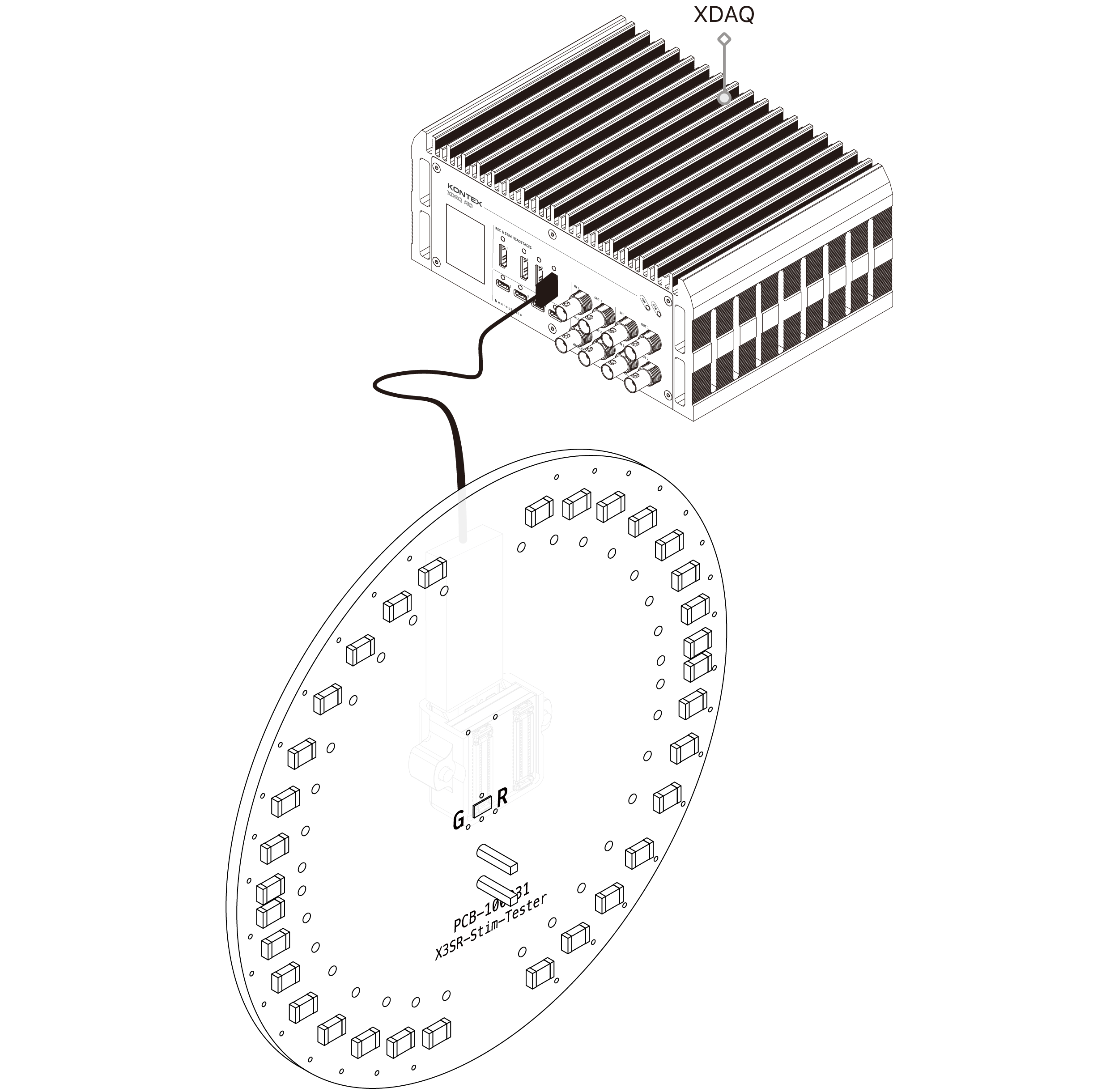
Due to the keyed connector pin orientation, the X3 Headstage supports left- and right-side connections. Users should alternate the connection orientation to verify stimulation waveforms on each side, ensuring complete testing while preventing incorrect insertion or electrical misalignment.
Dimension
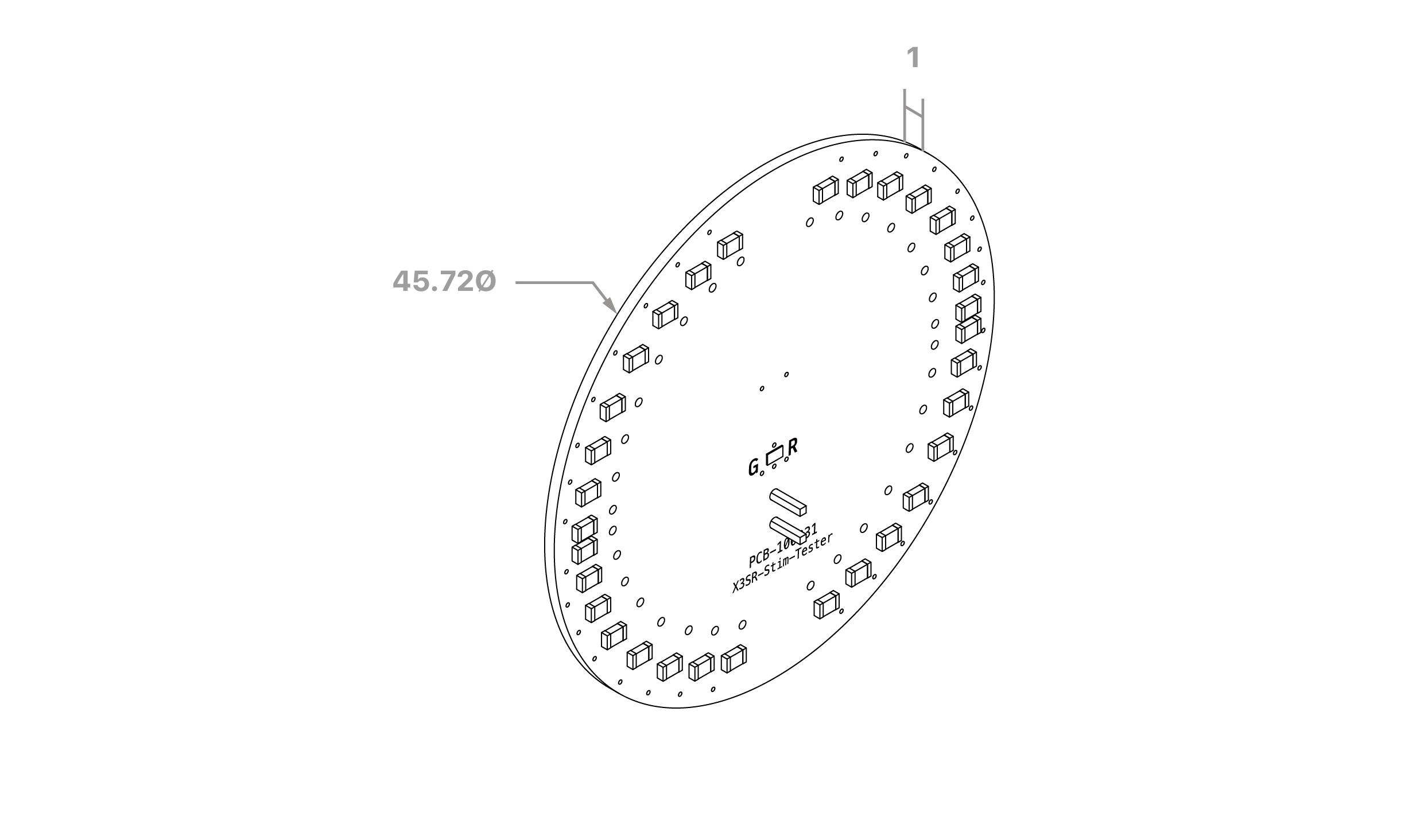
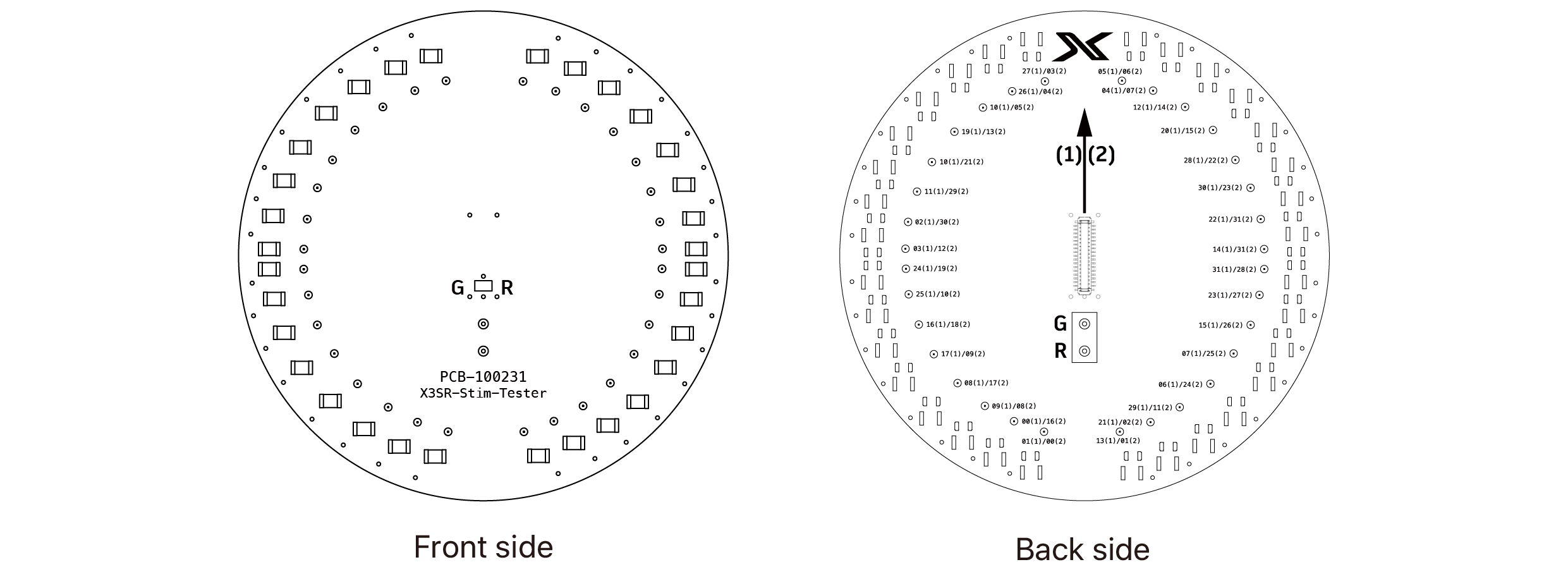
unit: mm
Compatibility
- Compatible with X3SR headstages
- Not compatible with non-stimulation X3 headstage variants
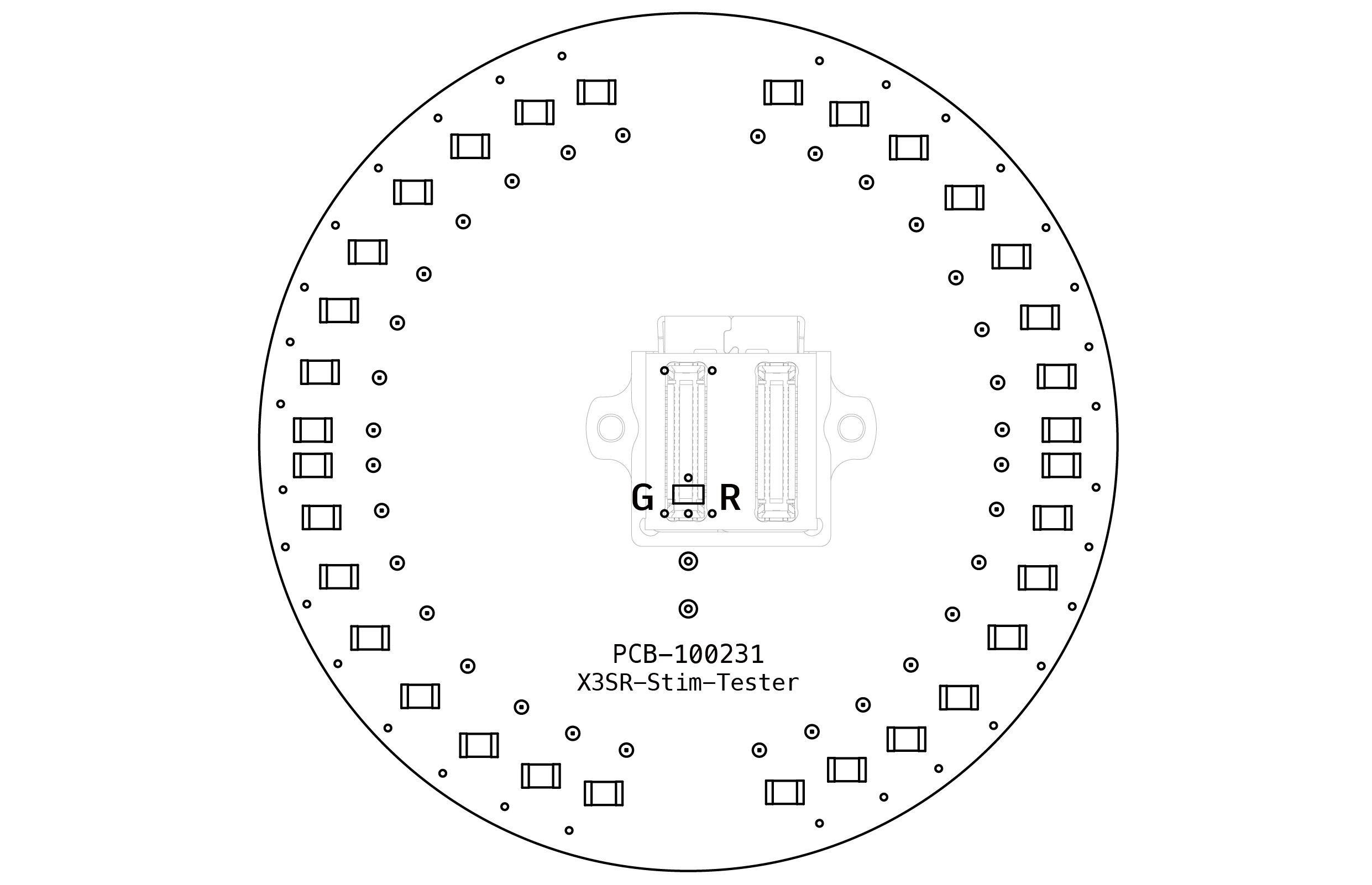
Ground & Reference Configuration
PCB-100231 X3SR-Stim-Tester
Revision Comparison
Beginning with Tester PCB Revision v1.1, the connector labels have been changed from (1)/(2) to A/B to provide a more intuitive correspondence with the headstage connectors.
| PCB Revision | Connector Labels |
|---|---|
NOTE: This is a labeling improvement only. All electrical connections, pin mappings, and channel assignments remain unchanged across PCB revisions.
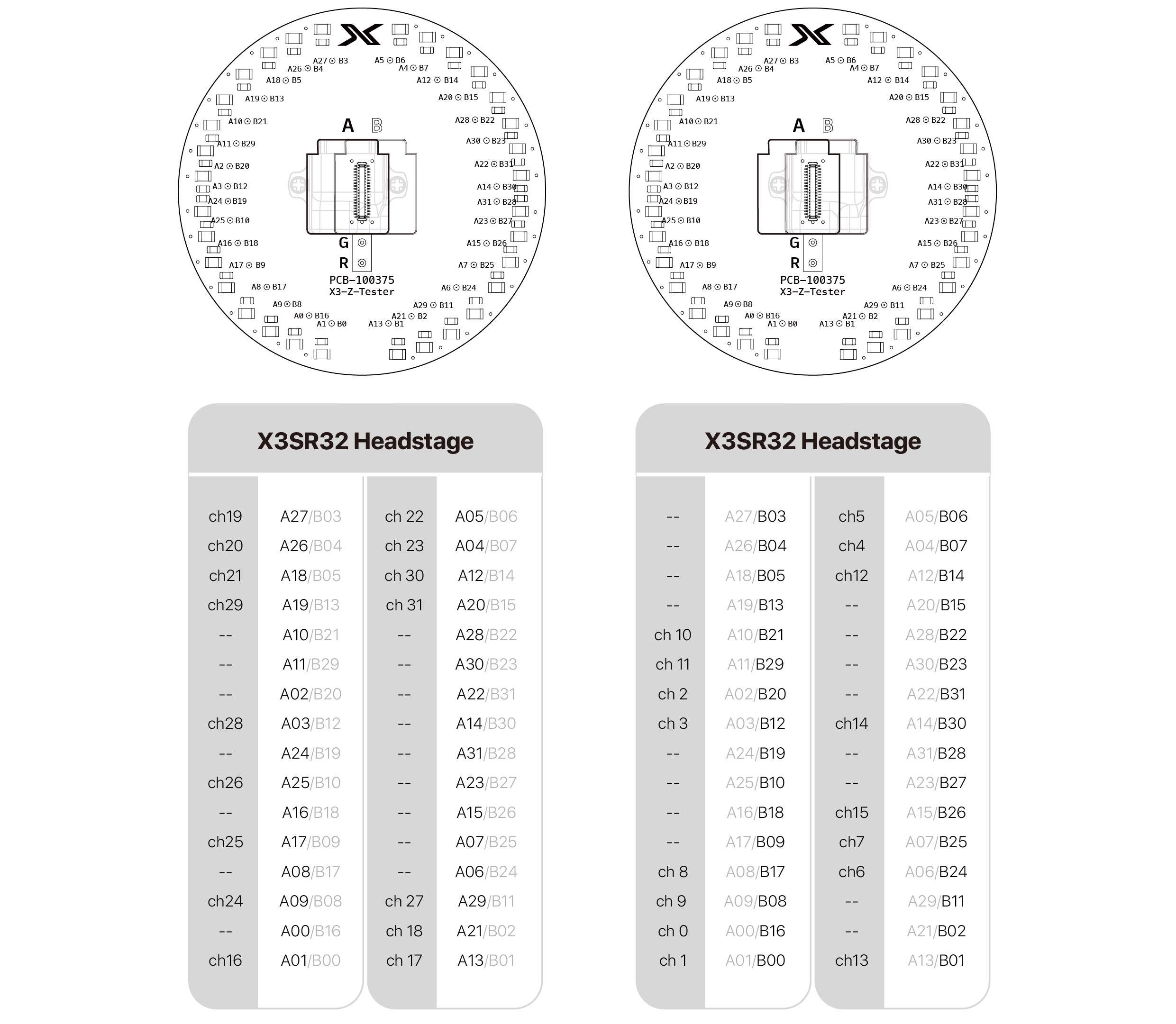
Pin map
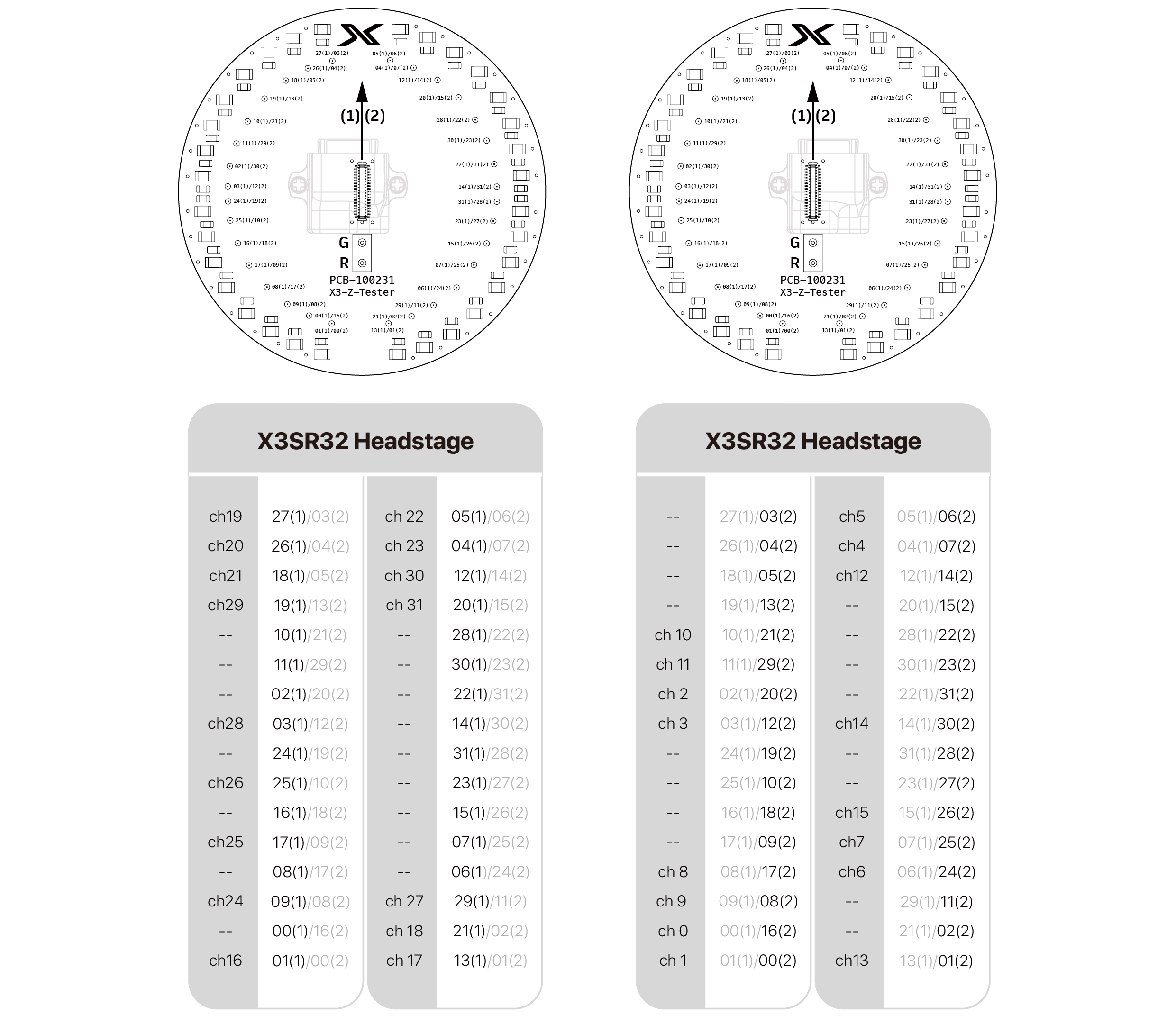
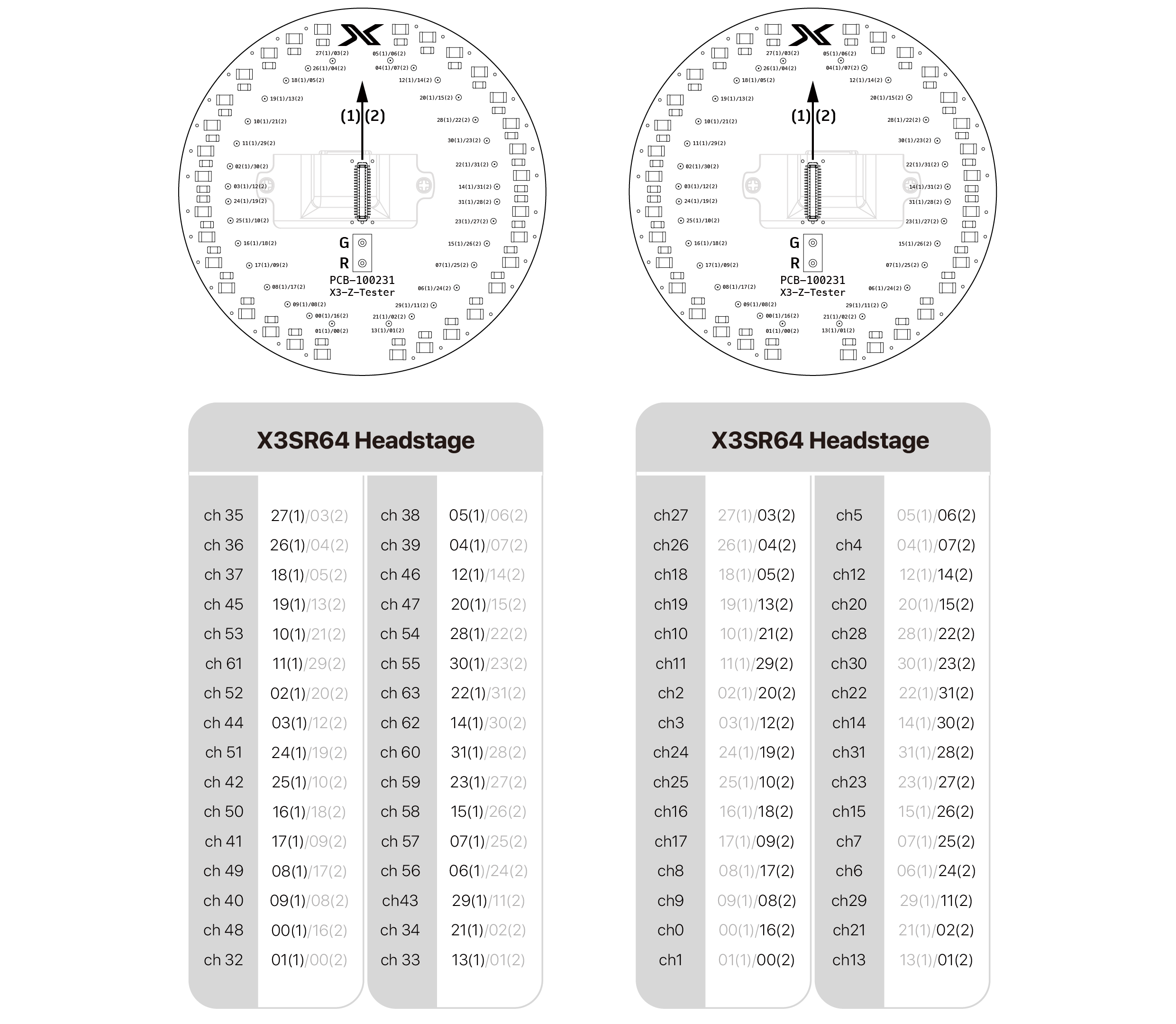
Connector orientation reference for the X3 Headstage Tester. Connector (1) corresponds to Headstage Connector A, and Connector (2) corresponds to Headstage Connector B. Refer to this relationship when using the pin mapping tables below.

Tester-Stim-X3 v1 with X3SR32
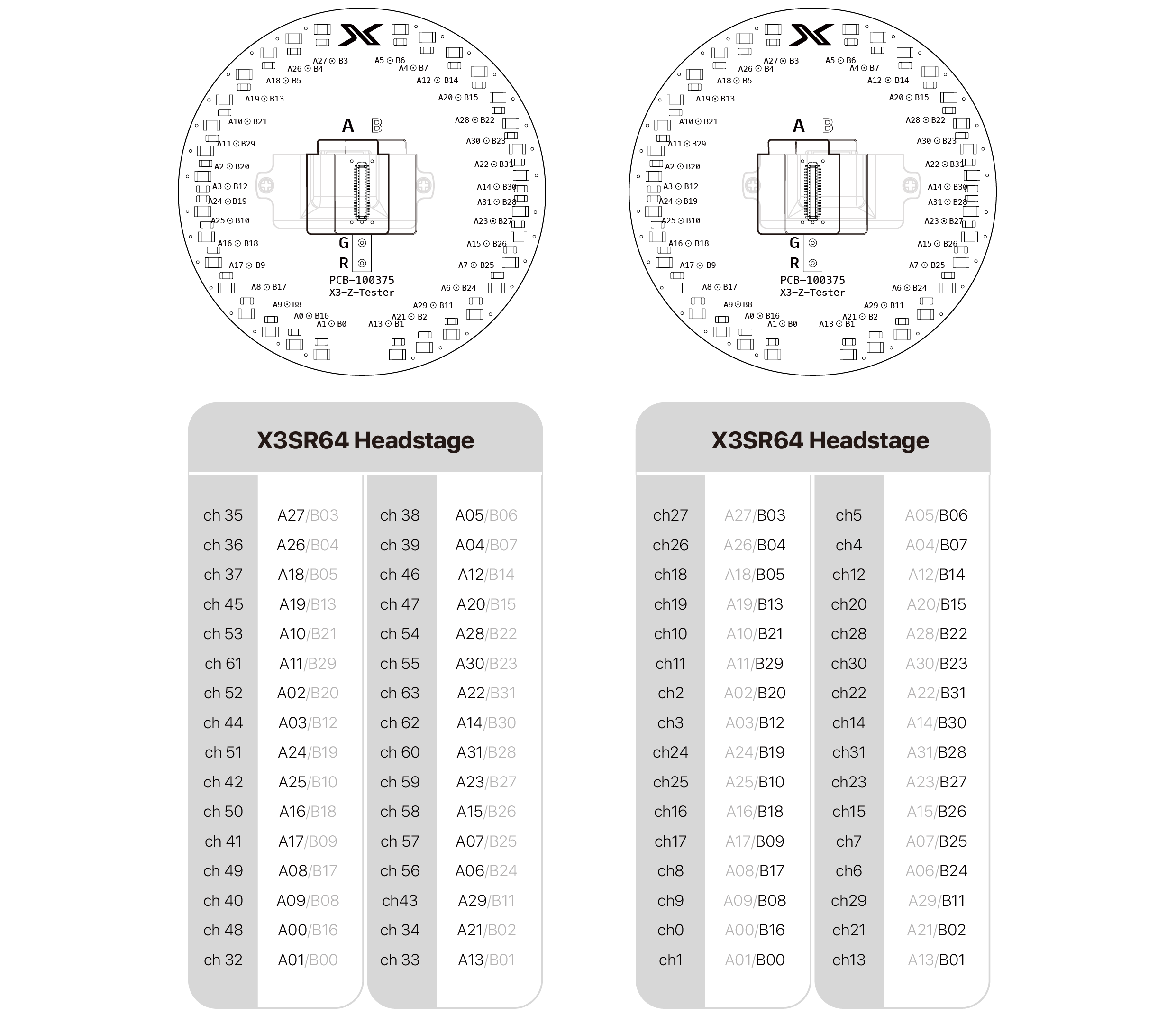
Tester-Stim-X3 v1 with X3SR64
PCB Silkscreen Label Correction
| Incorrect PCB Marking | Correct Pin Assignment |
|---|---|
The channel mapping table shown below has been verified and is correct. Always use the channel mapping table as the primary reference when identifying connector pin assignments.
Tester-Stim-X3 v1.1 with X3SR32
Tester-Stim-X3 v1.1 with X3SR64