Cable-IMU
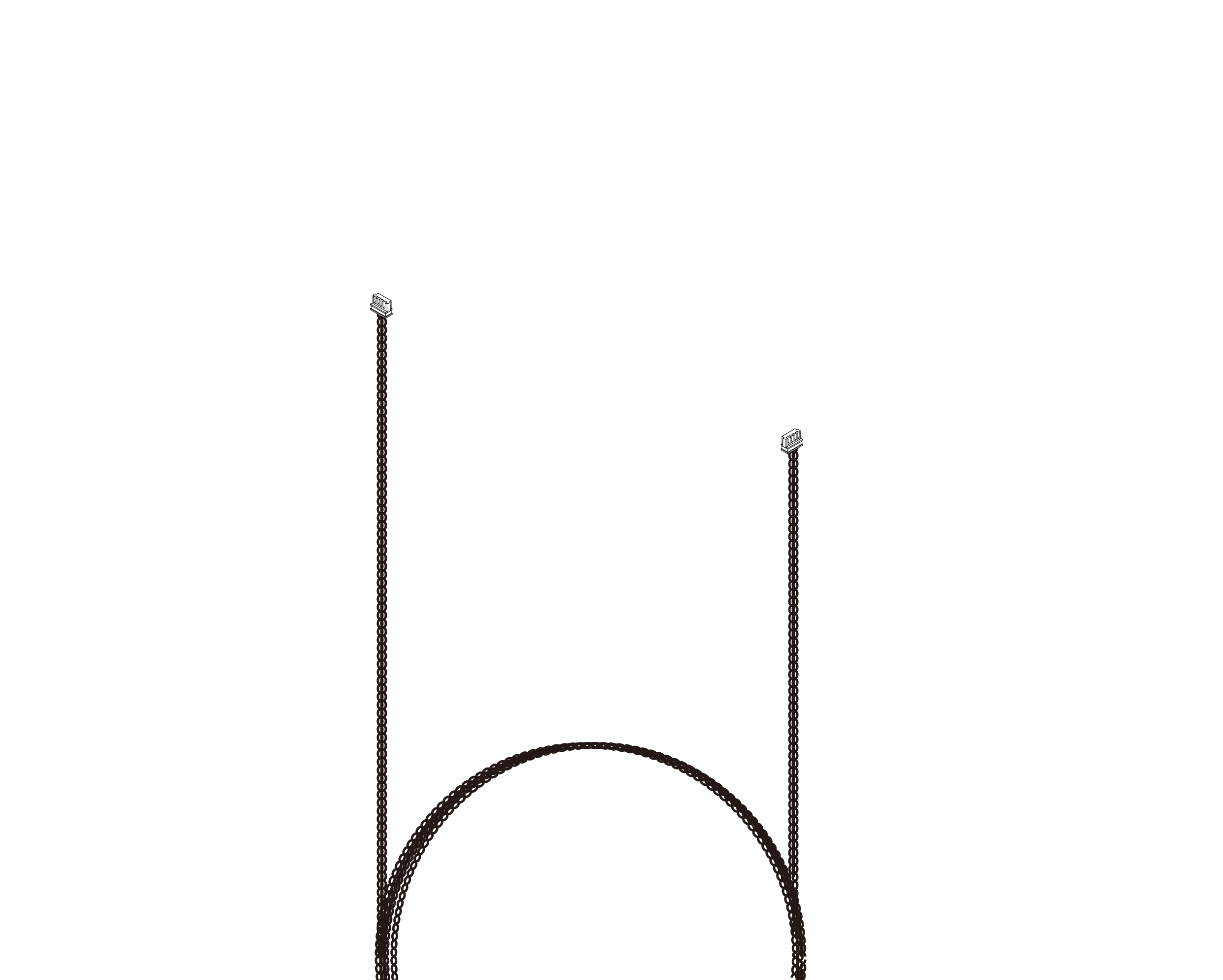
Overview
During freely moving experiments, animals may rotate continuously, causing tethered cables to twist and accumulate mechanical torque. Using the motion data received from the IMU Sensor, the Commutator Pro automatically rotates in the corresponding direction to compensate for the animal's movement. This active cable management minimizes cable twisting, reduces mechanical stress on implants and cables, and helps preserve natural behavior throughout long-term experiments.
The IMU Cable is dedicated exclusively to IMU communication and does not transmit neural recording, stimulation, or video signals.
To accommodate different laboratory layouts and experimental requirements, the IMU Cable is available in 1 m, 2.5 m, and 5 m lengths.
Dimension And Weight

unit: mm
| Length | Weight |
|---|---|
Key Features
Compatible Systems
Applications
Connection Orientation
GYRO Port Identification
| Item | Description |
|---|---|
| Connector Type | |
| PCB Label | |
| Function |
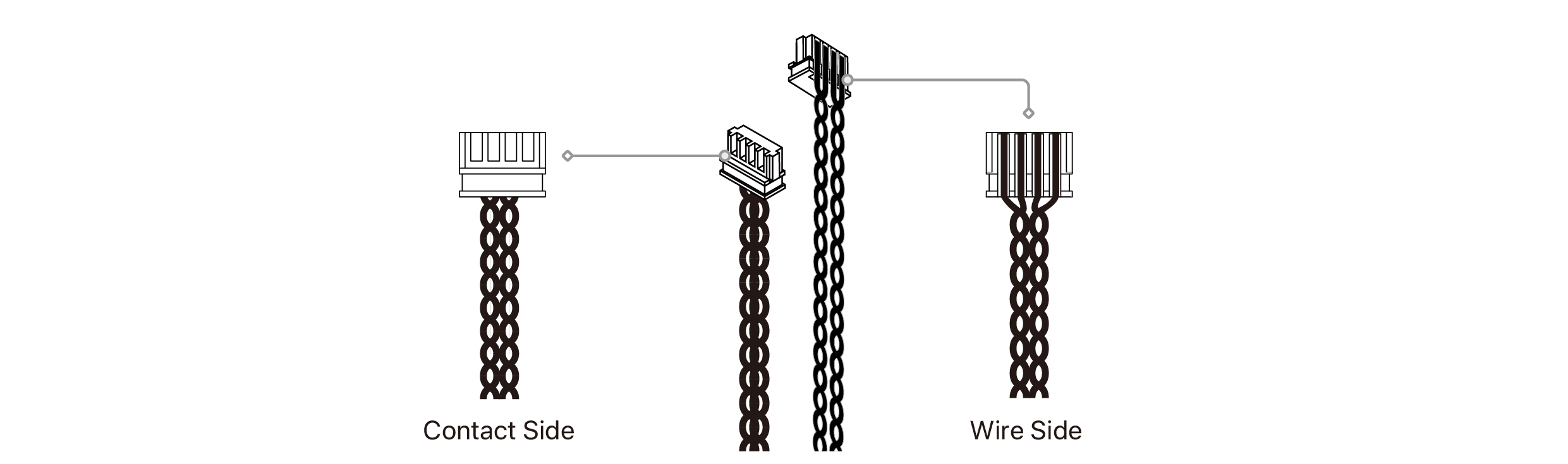
Connector Installation
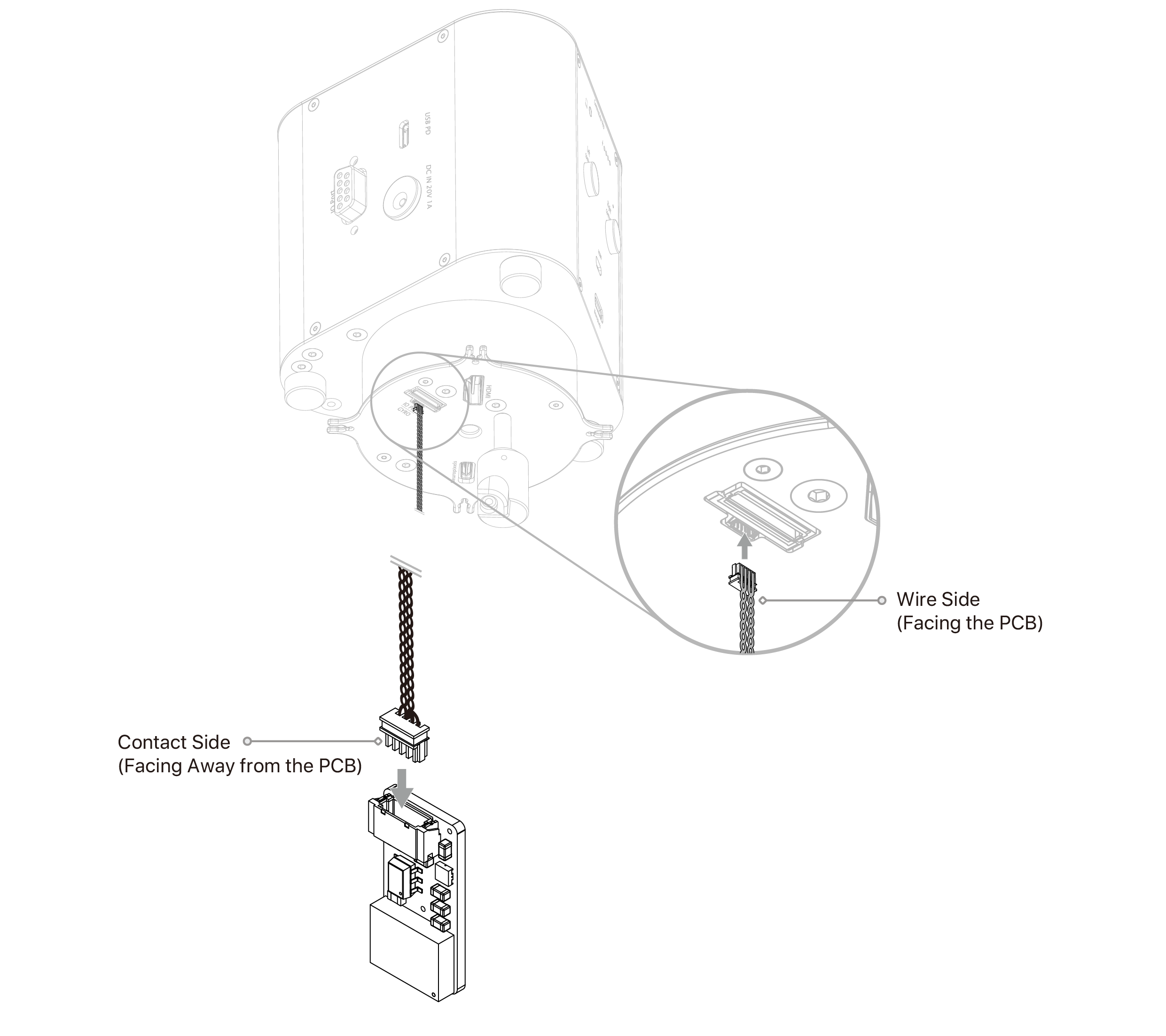
2. Identify the Wire Side and Contact Side of the IMU Cable connector.
3. Align the Contact Side with the GYRO receptacle as shown in the illustration.
4. Carefully insert the connector until it is fully seated.
5. Verify that the connector is securely connected before operating the system.
⚠ IMPORTANT :
• Connector Orientation
The GYRO interface uses a JST XSR 0.6 mm pitch connector with delicate miniature contacts. Always verify the connector orientation before insertion. Incorrect insertion may bend the connector pins or permanently damage the receptacle.
• Do Not Force the Connector
If resistance is encountered during insertion, stop immediately. Remove the connector, verify the orientation, and reinsert it gently.
• Proper Handling
Always hold the connector housing when connecting or disconnecting the IMU Cable. Do not pull directly on the cable.
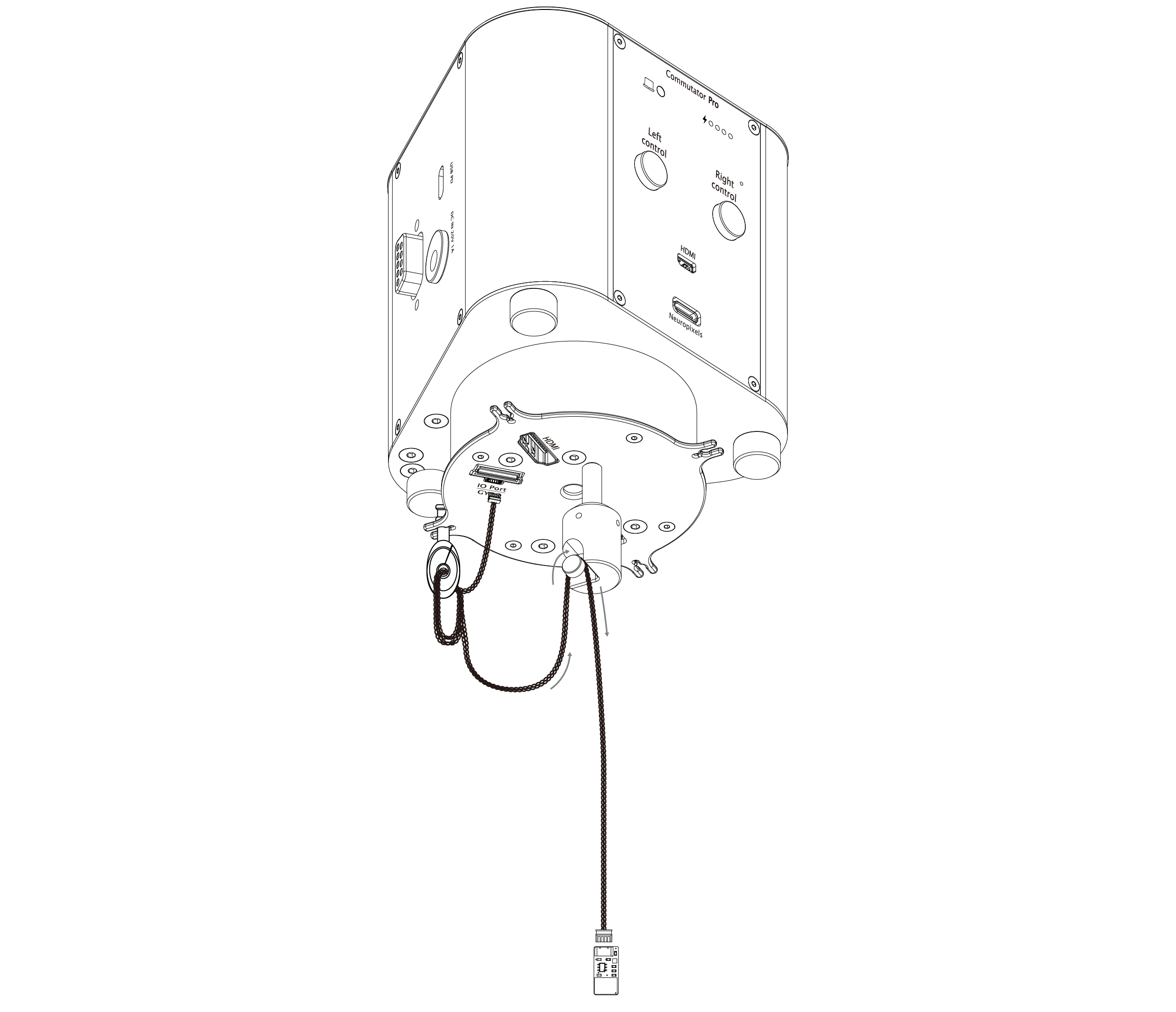
NOTE: Always secure any excess cable firmly into the integrated screw clips on the commutator as illustrated. To ensure maximum stability and prevent the tether from being accidentally pulled or strained during vigorous animal activity, it is highly recommended to pair your setup with the Fine-Cable Organizer Kit.
Proper anchoring eliminates cable tension, maintains unhindered rotation, and ensures optimal tracking sensitivity.
⚠ IMPORTANT: Ensure that all tether cables are securely routed and fastened through the integrated screw clips. Failure to properly anchor the cables may result in accidental disconnection or tether dislodgement during experimental procedures.
